Eduard-Maurer-Str. 13, D-16761 Hennigsdorf
03302 / 2 08 88 91
Produkte
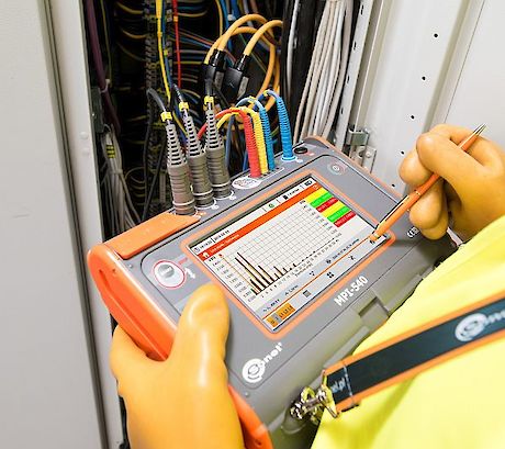
Sonel MPI-540 Serie

Das Sonel MPI 540 DIN/VDE 0100 Prüfgerät wird in fünf verschiedenen Paketen angeboten.

MPI 540 Start Das 0100 Prüfgerät in der Grundvariante ohne Stromzangen
MPI 540 Das 0100 Prüfgerät mit 3 flexiblen Stromzangen zur Leistungsmessung
MPI 540 PV Start Das 0100 Prüfgerät mit PVM-1 Adapter und Stromzange zur Messung von PV Anlagen ohne Zangen zur Leistungsmessung
MPI 540 PV dto. mit drei Leistungsmesszangen
MPI 540 PV Solar mit PV Messung, drei flexiblen Zangenstromwandlern zur Leistungsmessung und Einstrahlungssensor.
Weit mehr, als nur ein Installationsprüfgerät
Das große 7" Touch -Display mit 800x480 Pixeln - außergewöhnliche Ergonomie und Bedienkomfort
• Herausnehmbare Speicherkarte - einfaches vergrößern der Speicherkapazität
• Li-Ion Batterie - effizienter arbeiten durch längere Laufzeit
• Hinzufügen von Sprachmemos oder Fotos zu Messungen und Standort*
* Diese Funktion steht nach dem Softwareupdate zur Verfügung (kostenlos)
Messen aller Parameter in Bezug auf Erdung und Schutz gegen elektrischen Schlag - Nur noch ein Messgerät notwendig
• Zeitersparnis durch Schnellmessungen der Kurzschlussimpedanz mit the RCD ohne Auslösen (für einige Sekunden)
• Auto-Tests - Durchführung von automatischen aufeinanderfolgenden Messungen* - vereinfachte Messungen
• Blitzschnell von der Messung bis zum Prüfbericht
• Integriertes Hilfemenü - Das MPI enthält integrierte Hilfsansichten mit Messdiagrammen.
Dreiphasen-Netzwerk-Datenlogger - grundlegende Netzqualitätsanalyse
• Echtzeitanzeige der Netzwerkparameter - Sofortbewertung des Prüflings
• Parameter werden gemäß Klasse S der Norm EN 61000-4-30 gemessen - höchste Genauigkeit der Messungen
• Leistungsrechner* - Schnelle Beurteilung von Einsparmöglichkeiten
Mit den erweiterten Funktionen eines PQ-Analysators können anschaulich alle Parameter der Energieversorgung an den jeweiligen Anlagen erstellt werden.
Alle Messdaten der PQ-Analyse können auf SD-Karten abegespeichert werden.
Alle üblichen Schnittstellen werden unterstützt: USB, Bluetooth und WLAN.
Reichhaltiges Zubehör ist ebenfalls vorhanden, ein großer Teil bereits im Standard-Lieferumfang (s. Datenblatt)

- Datenblatt: Sonel MPI-540 Serie
- Preisliste: Sonel
Wir liefern